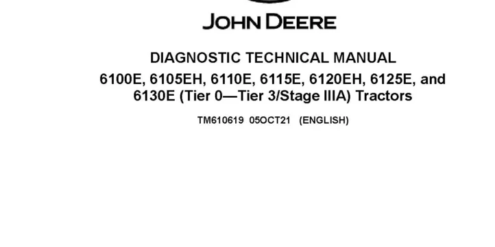
John Deere 6100E 6105EH 6110E 6115E 6120EH 6125E 6130E Tractors Diagnostic Manual TM610619
The John Deere 6100E 6105EH 6110E 6115E 6120EH 6125E 6130E Tractors Diagnostic Manual provides detailed diagnostic information for the 6100E, 6105EH, 6110E, 6115E, 6120EH, 6125E, and 6130E tractor models. It covers general information, diagnostic trouble codes, observable symptoms and system diagnostics, engine systems, fuel, air intake, exhaust and cooling systems, electrical systems and schematics, electrical components and connectors, electronic control units, drive systems and transmissions, steering and brakes, hydraulics, cab and open operator station systems, and special tools. The manual includes diagnostic information for engine operation, electrical circuits and components, control units, transmission and drive systems, steering and brakes, hydraulic systems, and operator station components.
Specifications: SM
- Brand: John Deere 6000 Series Tractors
- Type of Document: Diagnostic Manual
- Type of Equipment: Tractor
- Model: 6100E, 6105EH, 6110E, 6115E, 6120EH, 6125E, 6130E
- Manual Number: TM610619
- Language: English
- Format: PDF
Details:
Table of Contents
Introduction
- Foreword
General Information
- Safety
- General References
- Technical Specific References
Diagnostic Trouble Codes
- CCU Code Diagnostics
- ECU Code Diagnostics
- ICC Code Diagnostics
- PTR Code Diagnostics
Observable Symptoms and System Diagnostics
- General References
- Engine Diagnostics
- Fuel, Air Intake, Exhaust, and Cooling Diagnostics
- Electrical Diagnostics
- Electronic Control Unit Diagnostics
- Drive Systems and Transmission Diagnostics
- Steering and Brakes Diagnostics
- Hydraulic Diagnostics
- Cab/Open Operator’s Station Diagnostics
Engine
- General References
- Engine Calibrations, Preliminary Checks, and Operational Checks
- Engine Theory of Operation
- Engine Schematics
- Engine Component and Connector Information
- Engine Tests and Adjustments
Fuel, Air Intake, Exhaust, and Cooling
- General References
- Fuel, Air Intake, Exhaust, and Cooling Calibrations, Preliminary Checks, and Operational Checks
- Fuel, Air Intake, Exhaust, and Cooling Theory of Operation
- Fuel, Air Intake, Exhaust, and Cooling Schematics
- Fuel, Air Intake, Exhaust, and Cooling Component and Connector Information
- Fuel, Air Intake, Exhaust, and Cooling Tests and Adjustments
Electrical General and Theory of Operation
- General References
- Theory of Operation
Electrical Schematics
- General References
- Power Supply and Charging Schematic (SE01A)
- Neutral Start Schematic (SE01B)
- Engine Control Unit (ECU) Schematic (SE01C)
- Electrohydraulic Control Unit (EHC) Schematic (SE02)
- Vehicle CAN System Schematic (SE03)
- Instrument Cluster Control (ICC) Schematic (SE04)
- High/Low Beam Headlight Schematic (SE05A)
- SAE Style Turn and Warning Light Schematic (SE05B)
- EEC Style Turn and Warning Light Schematic (SE05C)
- License Plate Lights Schematic (SE05D)
- Brake Lights and Horn Schematic (SE05E)
- Cab Work Lights and Dome lights Schematic (SE05F)
- OOS Work Lights Schematic (SE05G)
- Air Conditioning System Schematic (SE06)
- Windshield Wiper System (SE07)
- Radio System Schematic (SE08)
- Power Outlet and Trailer Schematic (SE10)
- AMS System Schematic (SE12)
Electrical Components and Connectors
- General References
- Electrical Assemblies
- Sensors
- Lights
- Fuses
- Relays
- Motors
- Switches
- Resistors
- Diodes
- Electronically Actuated Mechanical Devices
- Fuses and Relays
- Ground Points
- Interconnects
- Wiring Harnesses
Electrical Tests and Adjustments
- General References
- Tests and Adjustments
Electronic Control Units
- General References
- Electronic Control Unit Calibrations, Preliminary Checks, and Operational Checks
- Electronic Control Unit Theory of Operation
- Electronic Control Unit Schematics
- Electronic Control Unit Component and Connector Information
- Electronic Control Unit Tests and Adjustments
- Chassis Control Unit (CCU)
- Engine Control Unit (ECU)
- Engine Interface Control Unit (EIC)
- Instrument Cluster Control Unit (ICC)
- Power Train Reverser (PTR)
Drive Systems and Transmissions
- General References
- Drive Systems and Transmission Calibrations, Preliminary Checks, and Operational Checks
- Drive Systems and Transmission Theory of Operation
- Drive Systems and Transmission Schematics
- Drive Systems and Transmission Component Information
- Drive Systems and Transmission Tests and Adjustments
Steering and Brakes
- General References
- Brake Calibrations, Preliminary Checks, and Operational Checks
- Steering Calibrations, Preliminary Checks, and Operational Checks
- Brakes Theory of Operation
- Steering Theory of Operation
- Brake Schematics
- Steering Schematics
- Brake Component and Connector Information
- Steering Component and Connector Information
- Brake Tests and Adjustments
- Steering Tests and Adjustments
Hydraulics
- General References
- Hydraulic Calibrations, Preliminary Checks, and Operational Checks
- Hydraulic Theory of Operation
- Mechanical Hitch Theory of Operation
- Mid-Mount SCV Theory of Operation
- Rear SCV Theory of Operation
- Hydraulic Schematics
- Hydraulic Component and Connector Information
- Hydraulic Tests and Adjustments
Cab/Open Operator’s Station
- General References
- Calibrations, Preliminary Checks, and Operational Checks
- Theory of Operation
- Schematics
- Component and Connector Information
- Tests and Adjustments
Special Tools
- General References
- Dealer Fabricated and Service Tools
- Section 240A
- Section 240B
- Section 240C
- Section 240D
Related posts:
 John Deere 6100E 6105EH 6110E 6115E 6120EH 6125E 6130E Tractors Repair Manual TM610719
 John Deere 6100E 6110E 6125E 6415 6615 Classic Tractors Diagnostic Manual TM800319
 John Deere 6110E 6125E 6415 6615 Classic Tractors Repair Manual TM800419
 John Deere 1654 1854 2054 2104 6165J 6185J 6205J 6210J Tractors Diagnostic Manual TM802219