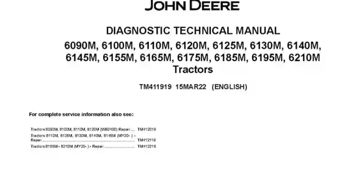
John Deere 6090M 6100M 6110M 6120M 6125M 6130M 6140M 6145M 6155M 6165M 6175M 6185M 6195M 6210M Tractors Diagnostic Manual TM411919
The John Deere 6090M 6100M 6110M 6120M 6125M 6130M 6140M 6145M 6155M 6165M 6175M 6185M 6195M 6210M Tractors Diagnostic Manual provides detailed diagnostic information for these tractor models from MY2020. It covers serial number, model year, and engine information, software update packages, CIU improvement programs, general information, diagnostic service codes, and observable symptoms and system diagnostics. The manual also covers engine systems, fuel and cooling systems, electrical systems, electronic control units, drivetrain and transmission systems, steering, brakes, hydraulic systems, suspension systems, operator’s cab, component information, and special tools.
Specifications: SM
- Brand: John Deere 6000 Series Tractors
- Type of Document: Diagnostic Manual
- Model Year: 2020, 2021, 2022
- Type of Equipment: Tractor
- Model: 6090M, 6100M, 6110M, 6120M, 6125M, 6130M, 6140M, 6145M, 6155M, 6165M, 6175M, 6185M, 6195M, 6210M
- Manual Number: TM411919
- Language: English
- Format: PDF
Details:
Table of Contents
Introduction
- Foreword
Information about Serial Number, Model Year, and Engines
- Information about Serial Number and Serial Number Reset
- Model Year Information
- Engine Information
Information about Software, Introduction and Content of the CIU Improvement Programs
- Information about the Software Update Packages
- Information about the Introduction and Content of the CIU Improvement Programs
General Information
- Safety
- General References
- References for Technical Information
- Diagnostic Philosophy
Diagnostic Service Codes
- ABV control software
- AIC Control Software
- CCU Control Software
- CLC Control Software
- CSA Control Software
- CSM Control Software
- CRU Control Software
- ECU_Level_33_34 – ECU Control Software (FT4/Stage IV/V) (Level 33/34)
- ECU_Level_16 – ECU Control Software (Tier 2/Stage II) (Tier 3/Stage IIIA) (Level 16)
- EIC Control Software
- ETC Control Software
- FCC Control Software
- GM2 Control Software
- GM4 Control Software
- GR6 Control Software (AMS)
- HCC Control Software
- HV1 Control Software
- ICA Control Software
- IR6 Control Software (AMS)
- JDL Control Software (AMS)
- JL2 Control Software (AMS)
- MFC Control Software
- NAV Control Software (AMS)
- OIC Control Software
- PDU Control Software
- PLC Control Software
- PTA Control Software
- PTF Control Software
- PTQ Control Software
- RPT Control Software
- SB1 Control Software (E-SCV I, Version 1)
- SB2 Control Software (E-SCV II, Version 1)
- SB3 Control Software (E-SCV III, Version 1)
- SB4 Control Software (E-SCV IV, Version 1)
- SBK Control Software (E-SCV XI, Version 1)
- SBL Control Software (E-SCV XII, Version 1)
- SBM Control Software (E-SCV XIII, Version 1)
- SCC Control Software
- SFA Control Software
- SMB Control Software
- TEC Control Software
- TEI Control Software
- TIH Control Software
- TIN Control Software
- TIQ Control Software
- TM1 Control Software (E-SCV I, Version 2)
- TM2 Control Software (E-SCV II, Version 2)
- TM3 Control Software (E-SCV III, Version 2)
- TM4 Control Software (E-SCV IV, Version 2)
- TMK Control Software (E-SCV XI, Version 2)
- TML Control Software (E-SCV XII, Version 2)
- TMM Control Software (E-SCV XIII, Version 2)
- VLC Control Software
- VTI Control Software (AMS)
- VTV Control Software
- VTV_AMS – VTV Control Software (AMS)
- XMC Control Software
- XSC Control Software
Observable Symptoms and System Diagnostics
- Engine
- Fuel, Air Intake, and Cooling Systems
- Electrical System
- Electronic Control Units
- Drive Train (without Transmission)
- PowrQuad Transmission
- AutoPowr / IVT TRANSMISSION
- CommandQuad Transmission
- Steering
- Brakes
- Hydraulic System
- Suspension Systems
- Operator’s Cab
Engine
- General Information
- Aftertreatment, Theory of Operation
- Tests and Adjustments
Fuel, Air Intake, and Cooling Systems
- General Information
- Fuel System, Theory of Operation
- Air Intake System, Theory of Operation
- Cooling System, Theory of Operation
- Cold-Weather Starting System, Theory of Operation
- DEF Cooling Circuit, Theory of Operation
- Viscous Fan Drive (Electrical), Theory of Operation
- Fuel, Air Intake, and Cooling Systems – Schematics
- Fuel, Air Intake, and Cooling Systems – Tests and Adjustments
Fuel, Air Intake, and Cooling Systems – Component Information
- Fuel System, Component Information
- Aftertreatment, Component Information
- Cooling System, Component Information
- Charge Air Circuit, Component Information
- Cold Start System, Component Information
- Transmission Oil Cooling Circuit, Component Information
Electrical System
- Electrical System – General Information
- Electrical System – Summary of References
- Electrical System – Electrical Theory of Operation
- 30A – Electrical System – Schematics
- 50AA – Starter Motor and Charging Circuit
- 50AC – Cold Start Aids
- 50BA – Road Lights
- 50BB – Worklights
- 50BC – Interior Lighting
- 50BD – Turn Signal and Warning Lights
- 50CA – Operator’s Seat
- 50CD – Heater/Ventilation/Air-Conditioning System
- 50CE – Audible Alarms
- 50CF – Radio
- 50CG – Cab Switch Module
- 50CH – Accessories
- 50DA – Power Outlet Sockets
- 50DB – Wiper
- 50EA – Greenstar Display and Implement CAN Bus
- 50EB – AutoTrac
- 50ED – JDLink Service ADVISOR Remote
- 50FA_Level_33_34 – 50FA – Engine Control (FT4/Stage IV/V) (Level 33/34)
- 50FA_Level_16 – 50FA – Engine Control (Tier 2/Stage II) (Tier 3/Stage IIIA) (Level 16)
- 50FB – Immobilizer
- 50FC_Level_33_34 – 50FC – Fuel System (FT4/Stage IV/V) (Level 33/34)
- 50FC_Level_16 – 50FC – Fuel System (Tier 2/Stage II) (Tier 3/Stage IIIA) (Level 16)
- 50GA – PowrQuad Transmission
- 50GB – AutoPowr/IVT Transmission
- 50GD – CommandQuad Transmission
- 50GH – Differential Lock
- 50GI – Front-Wheel Drive
- 50GJ – Rear PTO
- 50GK – Front PTO
- 50HA – Rear Hitch
- 50HB – E-SCV Selective Control Valves
- 50HF – Electro-Hydraulic Pickup Hitch (E-PUH)
- 50HH – Front Loader
- 50IA – Display
- 50JA – CAN Bus Systems
- 50JB – LIN Bus Module
- 50JC – Ethernet Systems
- 50KA – Suspended Front-Wheel Drive Axle
- 50LA – Brakes
- 50X – Ground Connections
- 50ZY – Wake-Up Voltage and Keep-Alive Voltage
- 50ZZ – Electronic Control Units
Electronic Control Units
- Electronic Control Units – General Information
- Electronic Control Units – Summary of References
- Electronic Control Units – Interactive Tests and Calibrations
- Electronic Control Units – Information on Programming
- Electronic Control Units – Theory of Operation
- Immobilizer Control Unit
- ABV control software
- AIC Control Software
- CCU Control Software
- CLC Control Software
- CRU Control Software
- CSA Control Software
- CSM Control Software
- ECU_Level_33_34 – ECU Control Software (FT4/Stage IV/V) (Level 33/34)
- ECU_Level_16 – ECU Control Software (Tier 2/Stage II) (Tier 3/Stage IIIA) (Level 16)
- EIC Control Software
- ETC Control Software
- FCC Control Software
- GM2 Control Software
- GM4 Control Software
- GR6 Control Software (AMS)
- HCC Control Software
- HV1 Control Software
- ICA Control Software
- IR6 Control Software (AMS)
- JDL Control Software (AMS)
- JL2 Control Software (AMS)
- MFC Control Software
- NAV Control Software (AMS)
- OIC Control Software
- PDU Control Software
- PLC Control Software
- PTA Control Software
- PTF Control Software
- PTQ Control Software
- RPT Control Software
- SB1 Control Software (E-SCV I, Version 1)
- SB2 Control Software (E-SCV II, Version 1)
- SB3 Control Software (E-SCV III, Version 1)
- SB4 Control Software (E-SCV IV, Version 1)
- SBK Control Software (E-SCV XI, Version 1)
- SBL Control Software (E-SCV XII, Version 1)
- SBM Control Software (E-SCV XIII, Version 1)
- SCC Control Software
- SFA Control Software
- SMB Control Software
- TEC Control Software
- TEI Control Software
- TIH Control Software
- TIN Control Software
- TIQ Control Software
- TM1 Control Software (E-SCV I, Version 2)
- TM2 Control Software (E-SCV II, Version 2)
- TM3 Control Software (E-SCV III, Version 2)
- TM4 Control Software (E-SCV IV, Version 2)
- TMK Control Software (E-SCV XI, Version 2)
- TML Control Software (E-SCV XII, Version 2)
- TMM Control Software (E-SCV XIII, Version 2)
- VLC Control Software
- VTI Control Software (AMS)
- VTV Control Software
- VTV_AMS – VTV Control Software (AMS)
- XMC Control Software
- XSC Control Software
Electrical Connectors, Wiring Harnesses and Components
- Electrical Connectors, Wiring Harnesses, and Components – General Information
- Electrical Components – Assemblies
- Electrical Components – Sensors
- Electrical Components – Miscellaneous Devices and Equipment
- Electrical Components – Fuses, Relays, and Diodes
- Electrical Components – Power Supply and Alternator
- Electrical Components – Monitoring and Signaling Devices
- Electrical Components – Electrical Motors
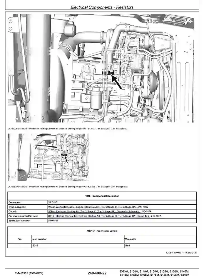
- Electrical Components – Resistors
- Electrical Components – CAN Bus Terminating Resistors
- Electrical Components – Switches
- Wiring Harnesses
- Wiring Harnesses – Battery Cables
- Wiring Harnesses – Antenna, Ethernet, Monitor, StarFire
- Connectors
- Connectors for Control Units
- Ground Points
- Electrical Components – Solenoid Valves and Solenoids
- Electrical Components – Other
Drive Train (without Transmission)
- Drive Train (without Transmission) – Operational Checks
- Drive Train (without Transmission) – Theory of Operation
- Drive Train (without Transmission) – Tests and Adjustments
AutoPowr / IVT TRANSMISSION
- AutoPowr/IVT Transmission – General Information
- AutoPowr/IVT Transmission – Operational Checks
- AutoPowr/IVT Transmission – Theory of Operation
- AutoPowr/IVT Transmission – Hydraulic Schematics
- AutoPowr/IVT Transmission – Tests and Adjustments
PowrQuad Transmission
- PowrQuad Transmission – General Information
- PowrQuad Transmission – Operational Checks
- PowrQuad Transmission – Theory of Operation
- PowrQuad Transmission – Schematics
- PowrQuad Transmission – Tests and Adjustments
CommandQuad Transmission
- General Information
- Operation and Preliminary Checks
- Theory of operation
- Schematic
- Diagnostic Tests and Adjustments
Drivetrain – Component Information
- Drivetrain (without Transmission) – Component Information
- PowrQuad Transmission – Component Information
- CommandQuad Transmission (CQ) – Component Information
Steering
- Steering – General Information
- Steering – Operational Checks
- Steering – Theory of Operation
- Steering – Schematics
- Steering – Tests and Adjustments
Brakes
- Brakes – General Information
- Brakes – Operational Checks
- Brakes – Theory of Operation
- Brakes – Schematics
- Brakes – Tests and Adjustments
Steering and Brakes – Component Information
- Steering – Component Information
- Brakes – Component Information
Hydraulic System
- Hydraulic System – General Information
- Hydraulic System – Operational Checks
- Hydraulic System – Theory of Operation
- Oil Filter, Additional Oil Reservoir, Charge Pump and Hydraulic Pump – Theory of Operation
- Rear Hitch – Theory of Operation
- Front Hitch – Theory of Operation
- Selective Control Valves (SCVs) – Theory of Operation
- Electro-Hydraulic Trailer Hitch (E-PUH) – Theory of Operation
- Hydraulic System – Schematics
- Hydraulic System – Tests and Adjustments
Hydraulic System – Component Information
- Hydraulic System – Component Information
Suspension Systems
- Suspension Systems – Operational Checks
- Suspended Front-Wheel Drive Axle – Theory of Operation
- Mechanical Cab Suspension – Theory of Operation
- Suspended Front-Wheel Drive Axle – Schematics
- Suspended Front-Wheel Drive Axle – Tests and Adjustments
- Mechanical Cab Suspension – Tests and Adjustments
Suspension Systems – Component Information
- Suspended Front-Wheel Drive Axle – Component Information
- Mechanical Cab Suspension – Component Information
Operator’s Cab
- Operator’s Cab – Operational Checks
- Operator’s Cab – Theory of Operation
- Operator’s Cab – Tests and Adjustments
Operator’s Cab – Component Information
- Air-Conditioning System – Component Information
Special Tools
- General Information
- Section 250A
- Section 250B
- Section 250C
- Section 250G
- Section 260A
- Section 260B
Related posts:
 John Deere 6090M 6100M 6110M 6120M WB2400 Tractors Repair Manual TM412019
 John Deere 6135M 6150M 6170M 6190M 6210M Tractors Diagnostic Manual TM808219
 John Deere 6135M 6150M 6170M 6190M 6210M Tractors Repair Manual TM808319
 John Deere 6155M 6165M 6175M 6185M 6195M 6210M Tractors Repair Manual TM412219