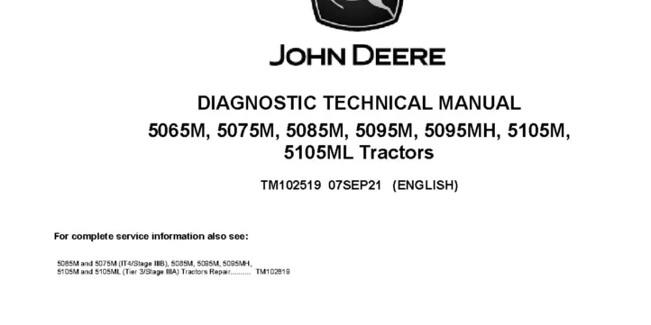
John Deere 5065M, 5075M (iT4/S3B) and 5085M, 5095M, 5095MH, 5105M, 5105ML (T4/S3A) Tractors Diagnostic Manual TM102519
The John Deere 5065M, 5075M (iT4/S3B) and 5085M, 5095M, 5095MH, 5105M, 5105ML (T4/S3A) Tractors Diagnostic Manual provides detailed diagnostic information for servicing and troubleshooting these tractor models, covering diagnostic trouble codes, observable symptoms, system diagnosis, engines, fuel and air, electrical systems, control units, transmissions, drive systems, steering and brakes, hydraulics, operator station, and service tools.
Specifications: SM
- Brand: John Deere 5000 Series Tractors
- Type of Document: Diagnostic Manual
- Emission Standards: Tier 4, Interim Tier 4, Stage IIIA, Stage IIIB
- Type of Equipment: Tractor
- Model: 5065M, 5075M, 5085M, 5095M, 5095MH, 5105M, 5105ML
- Manual Number: TM102519
- Language: English
- Format: PDF
Details:
Table of Contents
Introduction
- Foreword
General
- Safety
- General References
Diagnostic Trouble Codes
- CCU Code Diagnostics
- ECU Code Diagnostics
- HCU Code Diagnostics
- ICC Code Diagnostics
- PTR Code Diagnostics
Observable Symptoms
- Engine Symptoms
- Fuel and Air Symptoms
- Electrical Symptoms
- Control Unit Symptoms
- SyncShuttle Plus Transmission Symptoms
- SyncReverser Transmission Symptoms
- PowrReverser/PowrReverser Plus Transmission Symptoms
- Drive Systems Symptoms
- Steering and Brake Symptoms
- Hydraulic Symptoms
- Operator Station Symptoms
System Diagnosis
- Engine System Diagnosis
- Fuel and Air System Diagnosis
- Electrical System Diagnosis
- Control Unit System Diagnosis
- SyncShuttle Plus Transmission System Diagnosis
- SyncReverser Transmission System Diagnosis
- PowrReverser/PowrReverser Plus Transmission System Diagnosis
- Drive Systems Diagnosis
- Steering and Brake System Diagnosis
- Hydraulic System Diagnosis
- Operator Station System Diagnosis
Engines
- General Information
- Test Procedures and Adjustments
- Cooling System
- Engine Theory of Operation
Fuel and Air
- General Information
- Fuel and Air Theory of Operation
Electrical System
- General Electrical References
- Connector Information
- Harness Information
- SE01, SE02 – Power, Starting, PTM Fuel Injection
- SE03 – Accessory Power and SE04 – Horn
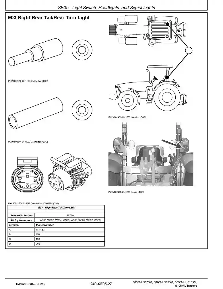
- SE05 – Light Switch, Headlights, and Signal Lights
- SE05A – SE05A – Cab Work Lighting
- SE05B – SE05B – Open Operator Station Work Lighting
- SE06 – Turn Signal Switch and Warning Lights
- SE07 – Light Switch, Headlights, Signal, License & Clearance Lights
- SE07A – SE07A – Cab Work Lighting (with Work Light Switches)
- SE07B – SE07B – Open Operator Station Work Lighting
- SE08 – Warning Light Switch and Turn Signal Lighting
- SE09, SE10, SE12 Junction Block Power, Trailer Connector, Loader Lights
- SE11 – Trailer Connector (with Implement Flood Light Connector)
- SE13, SE14, SE15 – Backup Alarm, Mid-Mount SCV, Power Outlets
- SE16 – Heating, SE17 – Air Conditioner, SE19 – Wipers
- SE20, SE21 – Wipers (Single Speed)
- SE22 – Dome Light, Radio, and SE23 – Air Seat
- SE24A, SE24B – StandardDeluxe Instrument Cluster Control (ICC) Unit
- SE25 – Diff Lock, Seat, Rear PTO, Wheel Speed, Ground Drive PTO
- SE27, SE28 – Mechanical Front-Wheel Drive (MFWD), Brake Switch
- SE26 – EH System Relay, and SE29 – EH Control (EHC) Unit
- SE29A – SE29A – Power Train Reverser (PTR) Control Unit Functions
- SE29B – SE29B – Chassis Control Unit (CCU) Functions
- SE29C – SE29C – Hitch Control Unit (HCU) Functions
- SE30, SE31 – 4045 and 5030 Engine Control Unit (ECU)
- SE32 – Controller Area Network Terminators/Service ADVISOR Connector
Control Units
- General References
- CCU – Chassis Control Unit
- ECU – Engine Control Unit
- HCU – Hitch Control Unit
- ICC – Instrument Cluster Control
- PTR – Power Train Reverser
Transmission
- Preliminary and Operational Checks
- Tests and Adjustments
- Theory of Operation
Drive Systems
- Preliminary and Operational Checks
- Tests and Adjustments
- Theory of Operation
Steering and Brakes
- Preliminary and Operational Checks
- Test and Adjustments
- Theory of Operation
Hydraulics
- Preliminary and Operational Checks
- Tests and Adjustments
- Theory of Operation
- Theory of Operation-Mono Block SCV Valves
- SCV Theory of Operation-Sectional Valves
Operator Station
- Preliminary and Operational Checks
- Tests and Adjustments
- Theory of Operation
Service Tools and Installing Test Equipment
- Dealer Fabricated Tools
- Service Tools and Kits
- Transmission – Install Test Equipment
- Drive Systems – Install Test Equipment
- Steering and Brakes – Install Test Equipment
- Hydraulics – Install Test Equipment
- Operator Station – Install Test Equipment
Related posts:
 John Deere 5075M (FT4/S3B), 5085M, 5100M, 5100MH, 5100ML, 5115M and 5115ML (iT3/S3B) Tractors Diagnostic Manual TM116519
 John Deere 5075M (FT4/S5) and 5090M, 5100M, 5100MH, 5100ML, 5115M, 5115ML (IT4/S3B, FT4/S4) Tractors Diagnostic Manual TM143619
 John Deere 6105D 6115D 6130D 6140D iT4/S3B Tractors Diagnostic Manual TM607319
 John Deere 5083EN, 5093EN and 5101EN T2/S2 and T3/S3A Tractors Diagnostic Manual TM112619