John Deere 6090MC-6110RC Tractors Diagnostic Manual TM406519
The John Deere 6090MC-6110RC Tractors Diagnostic Manual provides detailed diagnostic information for the 6090MC, 6090RC, 6100MC, 6100RC, 6110MC, and 6110RC tractor models from MY2014-2015. It covers general information, diagnostic trouble codes, observable symptoms and system diagnostics, engine, fuel and cooling systems, electrical systems, electronic control units, drivetrain, PowrQuad transmission, steering, brakes, hydraulics, machine-specific systems, suspension, operator’s cab, and special tools. The manual includes theory of operation, diagnostic schematics, component information, operational checks, tests and adjustments, and control software information. :contentReference[oaicite:0]{index=0}
Specifications: SM
- Brand: John Deere 6000 Series Tractors
- Type of Document: Diagnostic Manual
- Model Year: 2014, 2015
- Type of Equipment: Tractor
- Model: 6090MC, 6090RC, 6100MC, 6100RC, 6110MC, 6110RC
- Manual Number: TM406519
- Language: English
- Format: PDF
Details:
Table of Contents
Introduction
- Foreword
General Information
- Safety Measures
- General References
Diagnostic Trouble Codes
- AIC Control Software
- BLC Control Software
- CCU Control Software
- ECU Control Software
- EIC Control Software
- FCC Control Software
- HCC Control Software
- OIC Control Software
- PDU Control Software
- PTF Control Software
- PTQ Control Software
- RPT Control Software
- SFA Control Software
- SMB Control Software
- TEC Control Software
- TEI Control Software
- TIQ Control Software
- VTV Control Software
Observable Symptoms and System Diagnostics
- Engine
- Fuel, Air Intake, and Cooling System
- Electrical System
- Electronic Control Units
- Drivetrain (without Transmission)
- PowrQuad Transmission
- Steering system
- Brakes
- Hydraulic System
- Machine-Specific Systems
- Suspension Systems
- Operator’s Cab
Engine
- Aftertreatment, Theory of Operation
- Tests and Adjustments
Fuel, Air Intake, and Cooling System
- General Information
- Fuel System, Theory of Operation
- Air Intake System, Theory of Operation
- Cooling System, Theory of Operation
- Cold-Weather Starting System, Theory of Operation
- Fuel, Air Intake, and Cooling Systems – Tests and Adjustments
Fuel, Air Intake, and Cooling Systems – Component Information
- Fuel System, Component Information
- Cooling System, Component Information
- Charge Air Circuit, Component Information
- Cold Start System, Component Information
Electrical System
- Summary of References
- Electrical System – Theory of Operation
- 30A – Electrical Equipment – Diagnostic Schematics
- 50AA – Starter Motor and Charging Circuit
- 50AC – External Cold Start Aid
- 50BA – Lights
- 50BB – Worklights
- 50BC – Dome Light
- 50BD – Turn-Signal Lights
- 50CA – Operator’s Seat
- 50CB – Acoustic Alarms
- 50CC – Windshield and Rear Window Wipers
- 50CD – Heater/Ventilation/Air-Conditioning System
- 50CE – Sockets
- 50CF – Radio
- 50CH – Accessories (General Information)
- 50EA – TEC Control Software and Implement CAN Bus
- 50FA – Electronic Engine Control
- 50FB – Immobilizer
- 50FC – Fuel System
- 50GA – PowrQuad Transmission
- 50GH – Differential Lock
- 50GI – Front-Wheel Drive
- 50GJ – Rear PTO
- 50GK – Front PTO
- 50GL – Brakes
- 50HA – Rear Hitch
- 50HD – Suspended Front-Wheel Drive Axle
- 50HH – Front Loader
- 50IA – Display
- 50JA – CAN Bus Systems
- 50X – Ground Connections
- 50ZZ – Electronic Control Units
Electronic Control Units
- Electronic Control Units – General Information
- Electronic Control Units – Interactive Tests and Calibrations
- Electronic Control Units – Information on Programming
- Electronic Control Units – Theory of Operation
- Electronic Control Units – Diagnostic Schematics
- Electronic Control Units – Component Information
- Electronic Control Units – Tests and Adjustments
- Immobilizer – Immobilizer Control Unit
- AIC Control Software
- BLC Control Software
- CCU Control Software
- ECU Control Software
- EIC Control Software
- FCC Control Software
- HCC Control Software
- OIC Control Software
- PDU Control Software
- PTF Control Software
- PTQ Control Software
- RPT Control Software
- SFA Control Software
- SMB Control Software
- TEC Control Software
- TEI Control Software
- TIQ Control Software
- VTV Control Software
Electrical Connectors, Wiring Harnesses and Components
- Overview of Electrical Components and Harnesses
- Electrical Components – Assemblies
- Electrical Components – Sensors
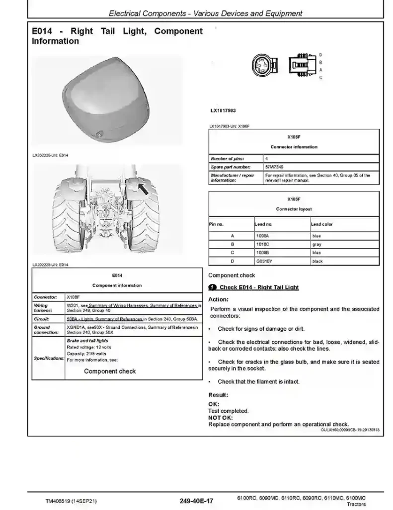
- Electrical Components – Various Devices and Equipment
- Electrical Components – Protective Equipment
- Electrical Components – Power Supply and Alternator
- Electrical Components – Monitoring and Signaling Devices
- Electrical Components – Relays
- Electrical Components – Electrical Motors
- Electrical Components – Resistors
- Electrical Components – Switches
- Electrical Components – Diodes
- Electrical Components – Wiring Harnesses
- Connector
- 40XGND – Ground Points
- Electrical Components – Solenoid Valves and Solenoids
- Electrical Components – Other
Drivetrain (without Transmission)
- Drivetrain (without Transmission) – Operational Checks
- Drivetrain (without Transmission) – Theory of Operation
- Drivetrain (without Transmission) – Tests and Adjustments
PowrQuad Transmission
- PowrQuad Transmission – General Information
- PowrQuad Transmission – Operational Checks
- PowrQuad Transmission – Theory of Operation
- PowrQuad Transmission – Schematics
- PowrQuad Transmission – Tests and Adjustments
Drivetrain – Component Information
- Drivetrain (without Transmission) – Component Information
- PowrQuad Transmission – Component Information
Steering system
- Steering – General Information
- Steering – Operational Checks
- Steering – Theory of Operation
- Steering – Schematics
- Steering – Tests and Adjustments
Brakes
- Brakes – General Information
- Brakes – Operational Checks
- Brakes – Theory of Operation
- Brakes – Schematics
- Brakes – Tests and Adjustments
Steering and Brakes – Component Information
- Steering – Component Information
- Brakes – Component Information
Hydraulic System
- Hydraulics – General Information
- Hydraulic System – Operational Checks
- Hydraulic System – Theory of Operation
- Oil Filter, Additional Oil Reservoir, Charge Pump and Hydraulic Pump – Theory of Operation
- Rear Hitch – Theory of Operation
- Front Hitch – Theory of Operation
- Selective Control Valves (SCVs) – Theory of Operation
- Independent Control Valves (ICVs) – Theory of Operation
- Hydraulic System – Schematics
- Hydraulic System – Tests and Adjustments
Hydraulic System – Component Information
- Hydraulic System – Component Information
Machine-Specific Systems
- Machine-Specific Systems – Operational Checks
- Machine-Specific Systems – Tests and Adjustments
Suspension Systems
- Suspension Systems – Operational Checks
- Suspended Front-Wheel Drive Axle – Theory of Operation
- Suspended Front-Wheel Drive Axle – Schematics
- Suspended Front-Wheel Drive Axle – Tests and Adjustments
Suspension Systems – Component Information
- Suspended Front-Wheel Drive Axle – Component Information
Operator’s Cab
- Operator’s Cab – Operational Checks
- Operator’s Cab – Theory of Operation
- Operator’s Cab – Tests and Adjustments
Operator’s Cab – Component Information
- Air-Conditioning System – Component Information
Special Tools
- General Information
- Section 250A
- Section 250C
- Section 260A
- Section 260B
- Section 280A
- Section 280B
Related posts:
 John Deere 6090MC-6110RC Tractors Repair Manual TM406619
 John Deere 1654 1854 2054 2104 6165J 6185J 6205J 6210J Tractors Diagnostic Manual TM802219
 John Deere 6E-1404 6E-1404-P 6E-1504-L 6E-1504-PL Tractors Diagnostic Manual TM706519
 John Deere 6100D 6110D 6115D 6125D 6130D 6140D Tractors Diagnostic Manual TM605119