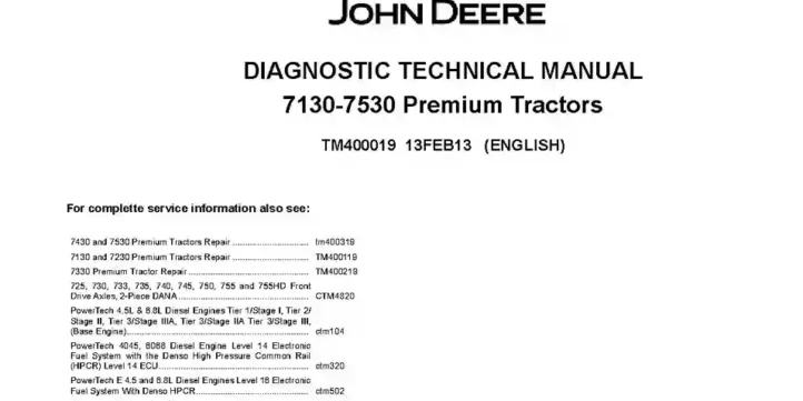
John Deere 7130 7230 7330 7430 7530 Premium Tractors Operation and Test Manual TM400019
The John Deere 7130 7230 7330 7430 7530 Premium Tractors Operation and Test Manual provides operation, testing, and diagnostic information for the listed Premium tractor models. The manual covers general information, diagnostic trouble codes, observable symptoms, system diagnostics, engine tests, fuel, air intake and cooling systems, and extensive electrical system diagnostics. It also covers electronic control units, AutoPowr/IVT and PowrQuad transmissions, drive train, steering and brakes, hydraulic systems, miscellaneous systems, operator’s cab, and special tools.
Specifications: SM
- Brand: John Deere 7000 Series Tractors
- Type of Document: Operation and Test Manual
- Type of Equipment: Tractor
- Region: North America
- Series: Premium
- Model: 7130, 7230, 7330, 7430, 7530
- Manual Number: TM400019
- Language: English
- Format: PDF
Details:
Table of Contents
FOREWORD
- SERIAL NUMBER BREAK 2008
GENERAL INFORMATION
- Safety Measures
- General References
DIAGNOSTIC TROUBLE CODES
- ATC – ATC Control Unit
- BCU – BCU Control Unit
- BIF – BIF Control Unit
- DSM – DSM Control Unit
- DTI – DTI Control Unit
- ECU – ECU Control Unit
- EPC – EPC Control Unit
- ETC – ETC Control Unit
- JDL – JDL Control Unit
- PLC – PLC Control Unit
- SIC – SIC Control Unit
- SSU – SSU Control Unit
- TCU – TCU Control Unit
- TEC – TEC Control Unit
- TEI – TEI Control Unit
- TSC – TSC Control Unit
- UIC – UIC Control Unit
- UIM – UIM Control Unit
- VTI – VTI Control Unit
OBSERVABLE SYMPTOMS
- Electrical System
- Electronic Control Units
- AutoPowr/IVT Transmission
- PowrQuad Transmission
- Drive Train (without Transmission)
- Steering and Brakes
- Hydraulic System
- Miscellaneous
- Operator’s Cab
SYSTEM DIAGNOSTICS
- Electronic Control Units
- PowrQuad Transmission
- Hydraulic System
- JDL – JDL – System Diagnostics
- VTI – VTI (GreenStar) – System Diagnostics
ENGINE
- General Information
- Operational Checks
- Tests and Adjustments
FUEL, AIR INTAKE AND COOLING SYSTEMS
- Tests and Adjustments
- A – Fuel System
- B – Air Intake System
- C – Cooling System
- D – Cold-Weather Starting Aids
ELECTRICAL SYSTEM
- SE01 – Starting Motor and Charging Circuit
- SE01A – Fuel Preheater
- SE01B – Electrical Starting Aid
- SE02 – BIF Control Unit (Basic Informator)
- SE03 – Horn
- SE04 – Operator’s Seat and Cigarette Lighter
- SE06 – Lights
- SE08 – Connector for Accessories
- SE09 – Radio Light, Dome Light, Console Light and Access Step Lights
- SE10 – ATC/ETC/HTC Control Units (Air Conditioning, Fan and Heater)
- SE14 – 3- and 7-Terminal Power Outlet Sockets
- SE15 – BCU Control Unit (Electronic Hitch Control)
- SE16 – BCU Control Unit (Basic Functions)
- SE17 – Signal Socket and Service Socket
- SE20 – TSC Control Unit (Suspension)
- SE21 – SIC Control Unit (Selective Control Valves)
- SE22 – CAN BUS Terminating Resistor
- SE23A – Level 14 ECU Control Unit (Electronic Engine Control) for 4-Valve Engine with HPCR
- SE23B – Level 16 ECU Control Unit (Electronic Engine Control) for 2-Valve Engine with HPCR
- SE26 – TCU Control Unit (Transmission Control with AutoPowr/IVT Transmission)
- SE26A – EPC Control Unit (Transmission Control with PowrQuad Plus or AutoQuad Plus Transmission)
- SE27 – UIC Control Unit (Transmission Control with AutoPowr/IVT Transmission)
- SE28 – PLC Control Unit (Electronic Park Lock with AutoPowr/IVT Transmission)
- SE29 – Electrical Outside Mirrors
- SE30 – JDL Control Unit (JDLink)
- SE32 – TEC Control Unit (ISOBUS)
- SE33 – GreenStar (AMS)
- SE35 – SSU Control Unit (AutoTrac)
- SE36 – UIM/VTI Control Units (GreenStar Display)
- SE37 – Electro-Hydraulic Pick-Up Hitch
- SE39 – PC6 Power Module (HF)
- SE40 – PC0 Power Module
- SE41 – PC5 Power Module
- SE42 – DTI Control Unit (CommandCenter)
- A – Component Information – Connectors and Contacts
- B – Component Information – Connectors (X001 to X249)
- C – Component Information – Connectors (X250 to X499)
- D – Component Information – Connectors (X500 to X749)
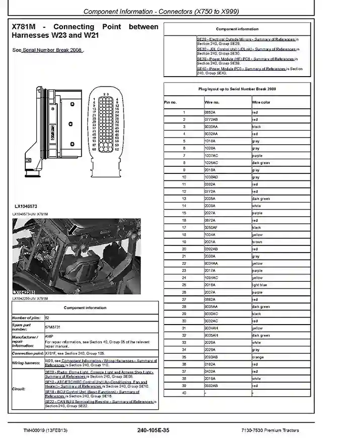
- E – Component Information – Connectors (X750 to X999)
- F – Component Information – Connectors (XGND)
- Component Information – Wiring Harnesses
- Component Information – Electrical Parts/Components
- A – Component Information – Electrical Parts/Components (Actuators)
- B – Component Information – Electrical Parts/Components (Sensors/Switches/Potentiometers)
- C – Component Information – Electrical Parts/Components (Fuses/Relays/Diodes)
- D – Component Information – Electrical Parts/Components (Headlamps/Lights)
- E – Component Information – Electrical Parts/Components (Other)
- Component Information – Ground Connections
- Component Information – CAN BUS Systems
ELECTRONIC CONTROL UNITS
- Operation and General Information on Diagnostics
- A – Interactive Tests
- B – Interactive Calibrations
- Information on How to Reprogram Control Units
- Data BUS Systems
- ATC – ATC Control Unit
- BCU – BCU Control Unit
- BIF – BIF Control Unit
- DSM – DSM Control Unit
- DTI – DTI Control Unit
- ECU – ECU Control Unit
- EPC – EPC Control Unit
- ETC – ETC Control Unit
- JDL – JDL Control Unit
- PC0 – PC0 Power Module
- PC5 – PC5 Power Module
- PC6 – PC6 Power Module (HF)
- PLC – PLC Control Unit
- SIC – SIC Control Unit
- SSU – SSU Control Unit
- TCU – TCU Control Unit
- TEC – TEC Control Unit
- TSC – TSC Control Unit
- UIC – UIC Control Unit
- UIM – UIM Control Unit
- VTI – VTI Control Unit
AUTOPOWR/IVT TRANSMISSION
- Operational Checks
- Tests and Adjustments
- Theory of Operation
POWRQUAD TRANSMISSION
- Operational Checks
- Tests and Adjustments
- Theory of Operation
DRIVE TRAIN (WITHOUT TRANSMISSION)
- Operational Checks
- Tests and Adjustments
- A – Front-Wheel Drive Clutch
- B – Differential
- C – Final Drives
- D – Rear PTO Options
STEERING AND BRAKES
- Introductory Checks
- Operational Checks
- Tests and Adjustments
- A – Hydrostatic Steering
- B – Brake Valve
- C – Rear Brakes
- G – AutoTrac
HYDRAULIC SYSTEM
- Operational Checks
- Tests and Adjustments
- Theory of Operation
- A – Oil Filter, Charge Pump and Hydraulic Pump
- B – Hitch
- C – Selective control valves (SCVs)
- D – Independent Control Valves (ICVs)
- E – Hydraulic block
MISCELLANEOUS
- Functional Tests
- Tests and Settings
- Operation
OPERATOR’S CAB
- Functional Tests
- Tests and Settings
- A – Ventilation/Heating
- B – Air-conditioning system
- C – ClimaTrak
- D – Cab Suspension
SPECIAL TOOLS
- Special Tools (Dealer-Fabricated)
- Special Tools (Available as Spare Parts)