John Deere 7515 Tractors Repair Manual TM8132
The John Deere 7515 Tractors Repair Manual provides detailed repair information for the 7515 tractor model. It covers general information and adjustments, engine removal and installation, fuel and air systems, cooling and exhaust, electrical systems, PowrQuad transmission, drive systems, steering and brakes, hydraulics, miscellaneous components, the operator’s cab, and special tools. The manual includes procedures for the fuel system, air intake, cooling system, charging and starting circuits, transmission controls, drive components, hydrostatic steering, brakes, hydraulic pump and charge pump, rockshaft, selective control valves, cab systems, and dealer-fabricated tools.
Specifications: SM
- Brand: John Deere 7000 Series Tractors
- Type of Document: Repair Manual
- Type of Equipment: Tractor
- Model: 7515
- Manual Number: TM8132
- Language: English
- Format: PDF
Details:
Table of Contents
Introduction
- Foreword
General information
- Specifications
- Adjustment
Engine
- Remove and Install Engine
Fuel System, Air Intake, Cooling and Exhaust
- Speed Control Link
- Fuel System
- Air Intake System
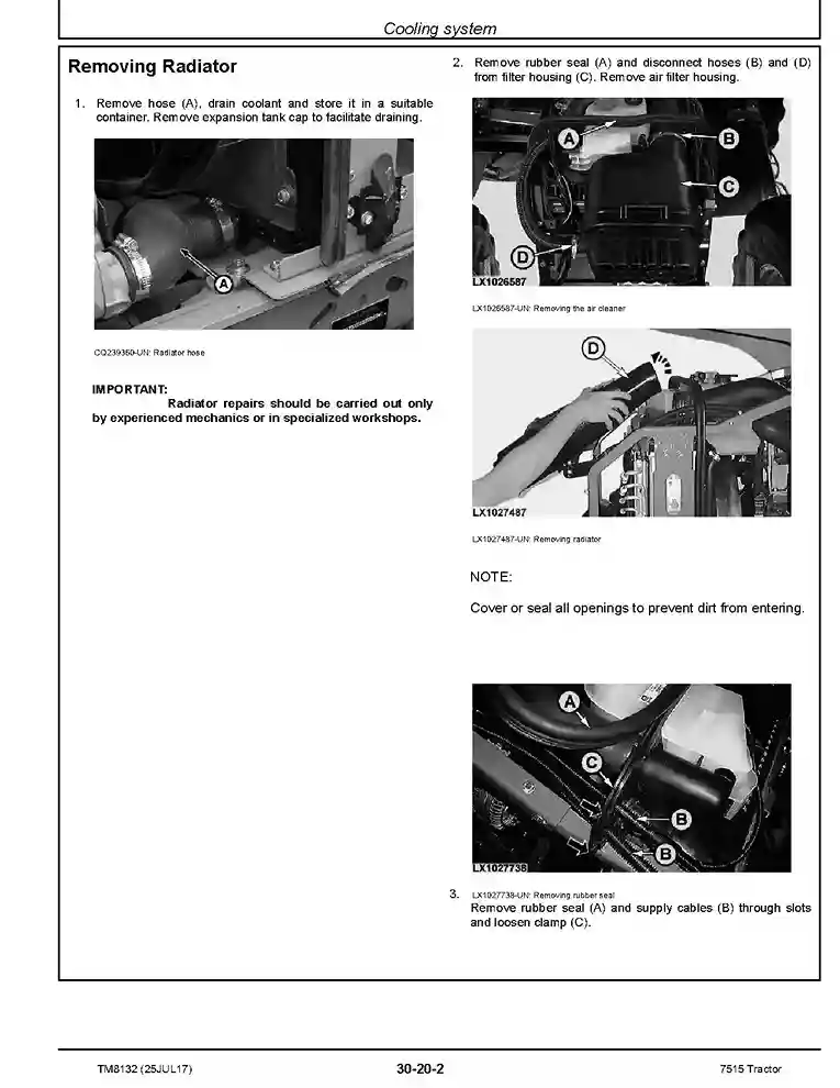
- Cooling system
- Exhaust System
Electrical System
- Connectors
- Harnesses
- Charging Circuit
- Starter Motor Circuit
- Fuses, Relays, and Switches
- Monitoring Systems
- Electric Components
PowrQuad Transmission
- Removing and Installing PowrQuad Module
- Transmission Selector Control
- PowrQuad Module
- Range Box-20 Series
Drive Systems
- Removing and Installing Component
- U-Jointed Shafts and Torsional Damper
- Front-Wheel Drive Clutch
- Differential
- Hydraulic Pump Drive
- Final Drives
- PTO Options
Steering and Brakes
- Hydrostatic Steering
- Brake Valve
- Rear Brakes
Hydraulic System
- Controls
- Hydraulic Pump and Charge Pump (PFC Hydraulic System)
- Cam Lobe Motor
- Rockshaft
- Selective Control Valves and Quick Couplers
Others
- Removing and Installing Components
- Main Chassis
- Front Wheels, Rear Wheels and Fenders
- Center Link Bracket and Swinging Drawbar
Operator’s Cab
- Removing and Installing Components
- Air Conditioning System
- Heating System
- Operator’s Cab
Special Tools (Dealer-Fabricated)
- Special Tools (Dealer-Fabricated)