
John Deere 9470RT 9520RT 9570RT Tracked Tractors Repair Manual TM146919
The John Deere 9470RT 9520RT 9570RT Tracked Tractors Repair Manual provides detailed repair information for the 9470RT, 9520RT, and 9570RT tracked tractor models with serial numbers from 917000. It covers general information, engine repair, fuel and air systems, exhaust and cooling, electrical systems, PowerShift transmission, drive train, rear axle assembly, brakes, steering, hydraulics, track frame and components, and the cab and open operator’s station. The manual includes repair procedures for transmission components, driveshafts and PTO systems, rear axle and final drive components, steering and braking systems, hydraulic pumps and valves, track components and suspension, HVAC, ComfortCommand seat, cab components, and dealer fabricated tools.
Specifications: SM
- Brand: John Deere 8000-9000 Series Tractors
- Type of Document: Repair Manual
- Type of Equipment: Tracked Tractor
- Model: 9470RT, 9520RT, 9570RT
- Heavy Tractors 8000-9000 Series Serial Number: 917000-
- Manual Number: TM146919
- Language: English
- Format: PDF
Details:
Table of Contents
Introduction
- Foreword
- Dealer Predelivery Information Form
General Information
- Safety
- General Information
Engine
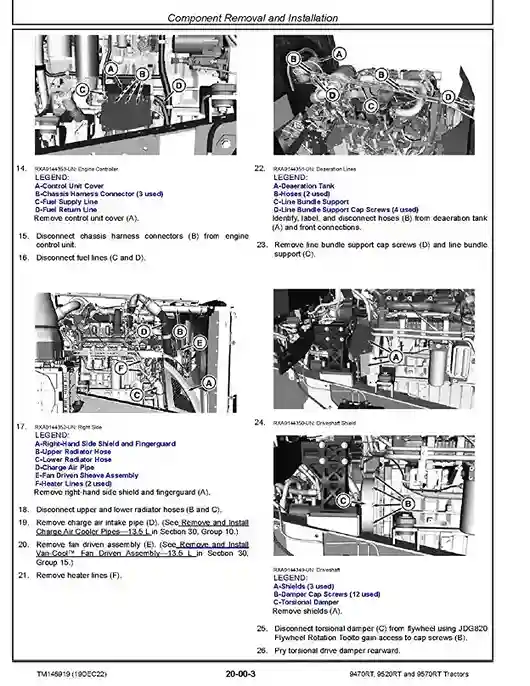
- Component Removal and Installation
- Engine Repair
Fuel, Air Intake, Exhaust, and Cooling
- Diesel Fuel System
- Air Intake System
- Auxiliary Drive System
- Radiator and Coolers
- Exhaust System
Electrical
- Connectors
- Charging Circuit
- Starting Circuit
- Relays, Fuses, Solenoids, and Switches
- Monitoring Systems and Sensors
- CommandARM
- Implement and Accessory Connectors
- Convenience and Accessory
PowerShift Transmission (PST)
- Component Removal and Installation
- In Tractor Repair
- Transmission Repair
- Assemble Transmission
Drive Train
- Component Removal and Installation
- Driveshafts
- PTO Clutch
- PTO Clutch Valve
- PTO Drop Box
Rear Axle Assembly
- Component Removal and Installation
- Outboard Planetary Final Drive
- Outboard Planetary Service Brakes
- Wheel Hub and Axle Housing
- Steering Differential Carrier
- Differential Case Steering Gears
- Input Pinion Housing
- Differential Case Drive Gears
Brakes
- Service Brakes
- Hydraulic Trailer Brake
Steering
- Steering Column
- Steering Pump
- Steering Pump Drive Gear Case
- Steering Motor
Hydraulics
- Component Removal and Installation
- Hydraulic System Repair
- Hydraulic Pump
- Gear Pump Assembly
- Filter Housings and Control Valves
- Hitch Valve, Selective Control Valves, and Couplers
- Rear Hitch
Miscellaneous
- Hood and Side Panels
- Platform Step Assembly
- Hitch Frame and Drawbar
Track Frame and Components
- Track
- Tension Cylinder and Accumulator
- Track Frame
- Track Suspension
Cab and Open Operator’s Station
- Component Removal and Installation
- Heating, Ventilating, and Air Conditioning (HVAC)
- ComfortCommand Seat
- Cab Door and Windshield
Dealer Tools
- Dealer Fabricated Tools
Related posts:
 John Deere 9470RT 9520RT 9570RT Tracked Tractors Diagnostic Manual TM147019
 John Deere 9RT470 9RT520 9RT570 Tracked Tractors Repair Manual TM165119
 John Deere 8100T 8110T 8200T 8210T 8300T 8310T 8400T 8410T Tracked Tractors Repair Manual TM1621
 John Deere 8RT 310 8RT 340 8RT 370 8RT 410 Tracked Tractors Repair Manual TM153919